Archive
As BugBrand I have been producing regularly since 2005. There is quite some history, some of which is shown here.
Nothing in this section is available to purchase – sorry, all long gone.
But the ideas continue to influence my designs today – it is all iterative.
Also check Archive.org for the older websites – original was 2005-09, then a new one 2009-2020.
Showing all 11 results
-
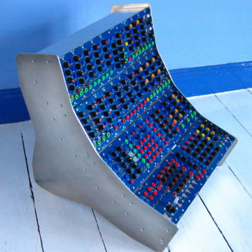
The Old Blues – Modular 2009-13
Out of stock
Read more -
Weevils (2005-2015)
Out of stock
Read more -
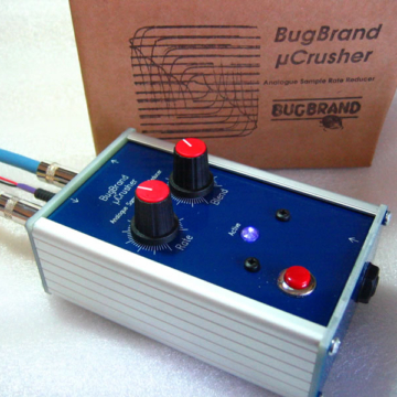
BugCrushers (2006-14)
Out of stock
Read more -
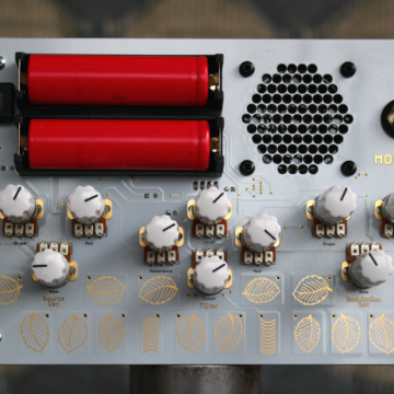
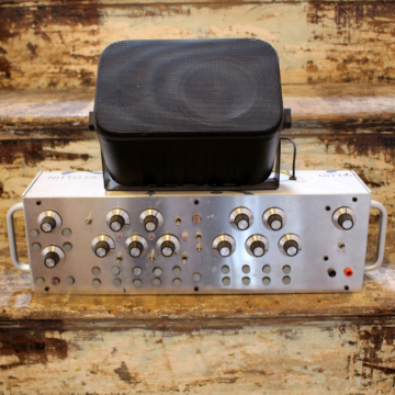
Molnet [archive]
£0.00 (Incl. VAT : £0.00)Out of stock
Read more -
![DRM1 Major Drum [Archive]](https://www.bugbrand.co.uk/wp-content/uploads/2019/10/DRM1_LRG-360x360.jpg)
DRM1 Major Drum [Archive]
£260.00 (Incl. VAT : £312.00)Out of stock
Read more -
![DRM1+X Expanded Major Drum [Archive]](https://www.bugbrand.co.uk/wp-content/uploads/2019/10/MDExpanded_LRG-360x360.jpg)
DRM1+X Expanded Major Drum [Archive]
£415.00 (Incl. VAT : £498.00)Out of stock
Read more -
![Spring Tanker [Archive]](https://www.bugbrand.co.uk/wp-content/uploads/2019/10/SpringTanker_LRG-360x360.jpg)
Spring Tanker [Archive]
£345.00 (Incl. VAT : £414.00)Out of stock
Read more -
![PEQ [archive]](https://www.bugbrand.co.uk/wp-content/uploads/2019/10/PEQ_LRG-360x360.jpg)
PEQ [archive]
£190.00 (Incl. VAT : £228.00)Out of stock
Read more -
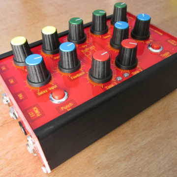
PT Delay 2011 (Archive)
£205.00 (Incl. VAT : £246.00)Out of stock
Read more -
![WorkshopCrusher [Archive]](https://www.bugbrand.co.uk/wp-content/uploads/2019/10/workshopcrush_LRG-360x360.jpg)
WorkshopCrusher [Archive]
£40.00 (Incl. VAT : £48.00)Out of stock
Read more -
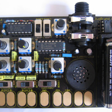
W.O.M. – Workshop Osc Machine
Out of stock
Read more