Description
The Sequence module is a powerful sequencing & clocking module with some interestingly different functions that take it away from regular binary approaches. The core builds around a binary logic counter chip, with clocking, reset & direction input options, while on the eight output steps it offers two gate busses and a voltage output with variable Up/Down glide. The rear of the module features several expansion headers allowing it to tie ‘behind the scenes’ to other clocking modules to create an integrated sequencing system.
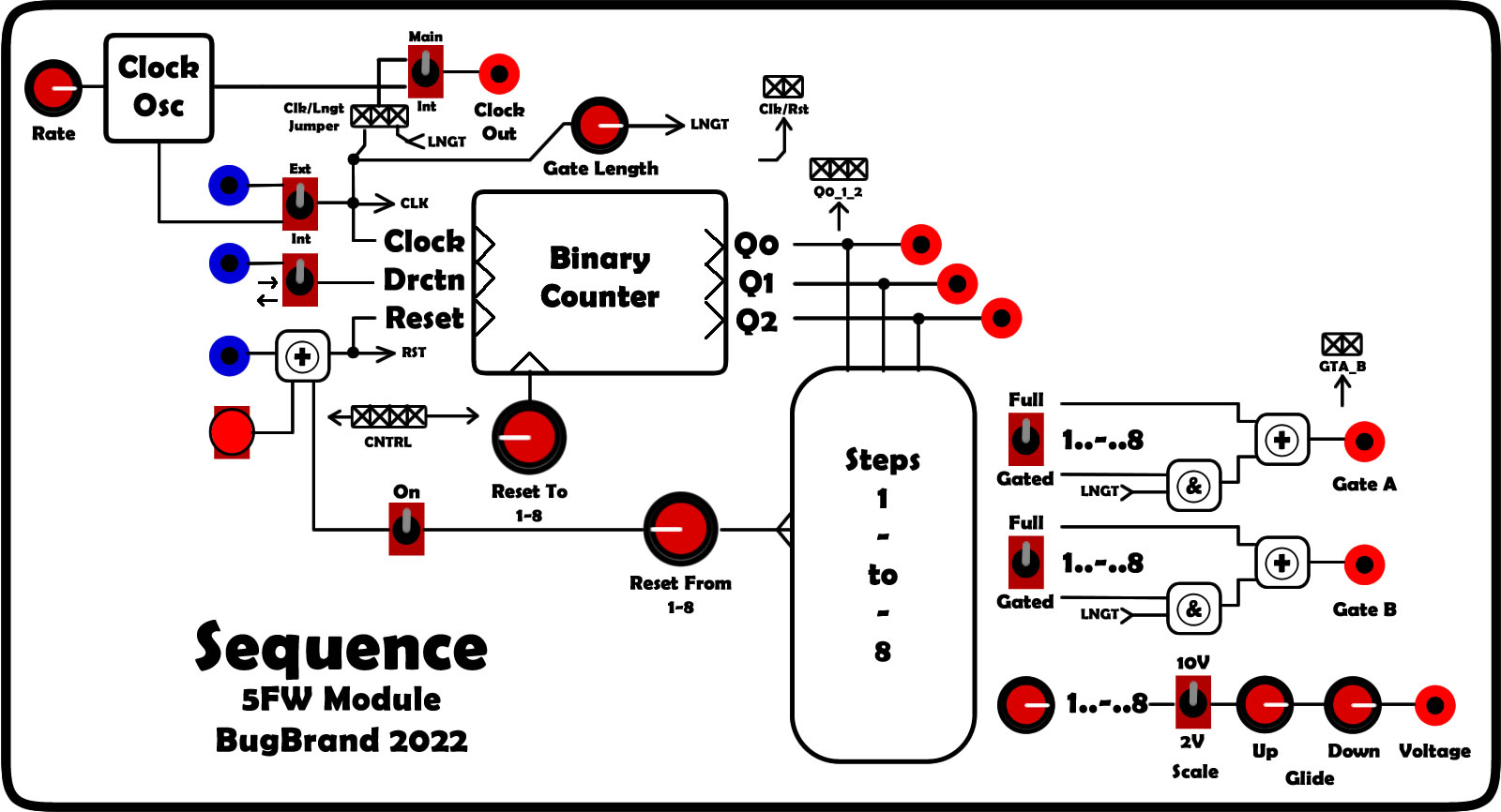
Have a check of the block diagram image above. Note that control inputs pass through comparators (threshold c.+1V) so can work with almost any signal.
- Clocking – the onboard Clock Oscillator goes from approx 0.65Hz/40BPM up to c.140Hz (8400BPM!). The main clock source is switchable between Internal (Clock Osc) or External source, and can clock fine at audio rates (tested up to 20kHz!).
The Clock Output is switchable between Internal or Main – allowing you to send out the Clock Osc & divide it before sending it back in to the External Clocking input (thanks Palle for that suggestion!). The Main option for this switch can also be changed to output the Lengthened clock pulse via a rear header (MAIN_CLK_OUT) which is set to CLK as standard.
The main clock bus (CLK) produces a 1mS pulse, while the internal Clock Osc produces a 50/50 duty pulse – both are approx 0V to +10V. - Gate Length – a pulse stretcher takes the CLK clock bus and stretches it in length with range from 2mS to 200mS for use with the Gate busses.
- Direction – the counter chip can count Up (right) or Down (left). This can be manually selected or externally controlled – with no or low logic input the counting moves up/right, while a logic high input makes it reverse. Note that a divide-by-two / flip-flop may be useful here to toggle from forwards to reverse.
- Reset – Reset can come from an external source, manual button, or the ‘Reset From’ step rotary with On/Off switch – this provides something akin to ‘Last Step’ though note it will feel different dependent on which direction the counter is moving. When any reset event occurs, the counter is ‘preset’ to the step set on the ‘Reset To’ rotary (akin to ‘First Step’).
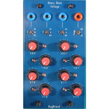
- Binary Outputs Q0-2 – the internal counter outputs a 3-bit binary signal that selects the active step of the sequencer, and this binary value is also output via the three Q outputs. These could, for example, be tied to the control inputs of the Binary Block Voltage to get it to follow the sequencer – or shuffle up their order, or divide some or… Outputs are approx 0V to +10V.
- Gate Busses – there are two identical gate busses, A & B. Each step switch can be set Up for Full, Centre for Off, or Down for Gated. A Full step means that the gate output is high for the whole step – akin to ‘tied’. For the Gated setting, the step is logic AND’ed with the Lengthened clock pulse to give shorter gate pulses – though note that if the Gate Length is set longer than the clocking period they will turn in to Full steps, remaining high through the step. Outputs are approx 0V to +10V.
- Voltage Output – the output can be set to range from 0V to +10V or scaled down to a +2V range for finer control. The voltage passes through a linear glide function with independent Up and Down controls. Ranges – Rise 2mS to 3S, Fall 1mS to 1.5S
The Rear Headers allow behind-the-scenes bussing to other clocking modules such as the DDSR or Dual Divide – contact me for custom cabling.
- CLK/RST – 2pin output – logic pulses from the Clock & Reset busses. The CLK line is ideally joined to the Clk buss input of other modules.
- Q0_1_2 – 3pin output – gate outputs mirroring the counter chip output & banana socket outputs.
- GTA_B – 2pin output – gate outputs mirroring the Gate buss outputs. 0 to +10V
- CNTRL – 4pin input – this allows control of the step selection from an external source. Pins 1 to 3 are Preset Inputs (Logic signal) which mirror the Reset To rotary function – note that the rotary needs to be set to Step 1 for proper operation in this case. Pin 4 is for a (P)Reset pulse which sums to the Reset buss. Note that a 2pin plug is placed over this header as a precaution so that it is not misidentified as the main Power connector!
Size: 5FW
Current: +ve 30mA, -ve 5mA