The system is built around voltages – static or fluctuating – so gaining an understanding of approaches and behaviours should help to demystify such terminology. Remember that an electronic sound is simply a voltage oscillating at a rate between 20 and 20,000 times per second (20Hz to 20kHz).
The system Power is based on an external 12V DC brick connected to the rear DC socket, while inside the frame this is converted to the bipolar (twin rail) +/-15V system power via a DCDC converter. This supply is then distributed internally on a PCB distribution bus to individual MTA100 power headers to which the module power cables are connected.
These system power voltages can be considered as ‘boundaries’ for signals within the system with the 0 Volt being the central point. Signal amplitudes within the system are standardised to 10V peak-to-peak (10V P-to-P) with the approach of outputting signals at full amplitude and applying any attenuation at the destination. Signals are generally either Unipolar or Bipolar and it is important to note these differences when it comes to patching:
•+/-5V = BIPOLAR – the signal swings from -5V to +5V, centred around 0V
eg. VCO
•0-10V = UNIPOLAR – the signal moves from 0V to +10V
eg. Envelope
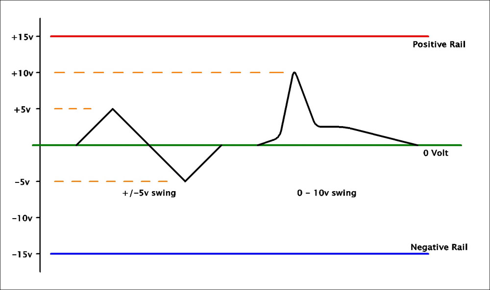
Of course, there can be slight exceptions to note – signals coming from a VCA may well be less than 10V P-to-P (unless the VCA is ‘fully open’), adding resonance via the Filters can increase amplitude and mixing several full-scale signals together can result in larger total swings. But you always have plenty of headroom before ‘hitting the rails’ (as signals can never exceed the bounds of the system power).
In terms of the Reds/Standalones – the aim is to bring external signals up to +/-5V amplitude as soon as possible via an input gain stage. All subsequent processing is dealt with exactly as if it were in modular form.
Connections:
All signals within the system are patched with 4mm Banana cables and sockets. All signals, being voltages, can be freely patched, but it can help to distinguish between the two major groups of functions:
•Main Path – Typically a signal input / output functional block to which some form of process is applied. A Filter, for example, could have one Main Path input and one Main Path output and within the functional block the process of filtering is applied. I have previously called this the Audio Path, but most modules are DC-coupled, meaning that they can equally process audio or sub-audio voltages.
•Control – This is a signal which combines with the settings of the function control dials to automate processes and is the basis of ‘voltage control’. Again taking a Filter as an example, the Frequency CV input (attenuated and/or inverted via the modulation depth setting) is summed with the setting of the main Frequency control dial to determine the operating Cutoff Frequency. You can think of a Control signal as being an automated knob twiddler and these can work at sub-audio or audio rates.
If you consider a module as a functional block, it will generate or process an audio (or sub-audio) signal via the Main Path, with the behaviour being governed by combination of knob settings and any Control signals applied.
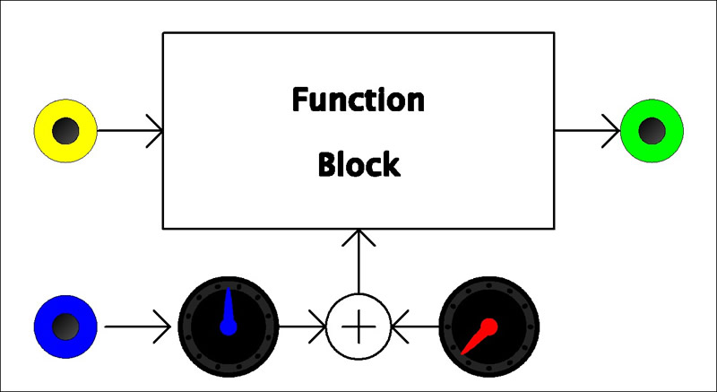
Colours play a key role in helping to quickly identify functions within the system. Sockets can generally be classified as follows:
| ..Main Path.. | ..Control.. | |
| Input | Yellow | Blue |
| Output | Green | Red |
Colours also help identify the function of dials:
•Red/Orange – for the main module control functions
•Yellow/Green – for input/output level control (eg. Mixing)
•Blue – solely for CV modulation depth
In all areas there can be exceptions and blurred boundaries – full details are given in individual Module descriptions. Simply note that voltages can function as Main Path and/or Control signals depending on what they are patched to – a VCO can be sound source and/or a modulator, for example. Also note that sub-audio signals may contain useful audio components eg. the transition of a clock signal can make a great source for a filter.
Modulation:
Any parameter that can be voltage controlled will have at least two control dials plus one or more CV input. One dial (typical colour Red/Orange) will act as the Master control, sweeping the function over its typical range, while the blue Modulation Depth control will set the amount of modulation from its respective CV input. Some modules have an additional ‘full-range’ CV input without level control, with these typically being for unattenuated or 1V/Oct response.
Blue controls set modulation depth. In early module designs (such as for SynthVoice) these were typically ‘attenuverting’ – a combination of Attenuating and Inverting – whereas more recent designs tend to try to include a dedicated polarity switch which also allows for easy muting.
For the attenuverting type – moving from the central zero position, clockwise rotation gives increasing modulation to unity (times one), while moving anti-clockwise inverts the modulation signal up inverted unity (times minus one). [Note that it can be hard to dial in exactly zero modulation via the dial – in such cases, the input cable can easily be removed for true zero.]
When considering inversion, note that it occurs around the 0V centre so unipolar or bipolar signals will behave as follows:
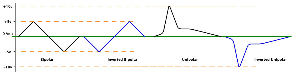
It is important to consider the waveform’s behaviour when applying it as a modulation signal. The modulation voltage (after input depth control) is summed with the value set by the main control dial,with positive voltages adding to the main sum and negative voltages subtracting. As such:
•A bipolar +/-5V signal will add and subtract from the master control setting.
For full control sweep, set the main control to a central position with CV full (or inverted).
•A 0 to +10V signal will add to the master control setting.
For full control sweep, set the main control to zero and apply full positive CV modulation.
•An inverted unipolar signal (0V to -10V) will subtract from the master control setting.
For full control sweep, set the main control to full and apply full inverted CV modulation.
As previously mentioned, signals are generally output at full 10V p-to-p amplitude allowing them to be split to more than one different destination, with the possibility of different attenuation settings at each destination. Banana cables allow quick and easy stacking of connections with the proviso:
| You can split one signal to several different destinations |
| eg: The output of a VCO could be patched both to the Main Path input of a VCF and also to the Frequency Modulation CV input |
| but |
| You cannot combine more than one signal into one input |
| eg: Two VCO outputs should not be combined by ‘mixing’ at the VCF’s mainpath input – use a mixer (eg. DC Mixer in Dual Mixing module) |
Saying that…
1) gate/clock outputs all now have series diodes which means you can passively mix these – it is a passive OR gate.
2) all outputs feature a universal output impedance (470 ohms) and built in short-circuit protection – so ‘passive’ / ‘stack’ mixing can be experimented with, it just won’t give ‘proper’ results.