Description
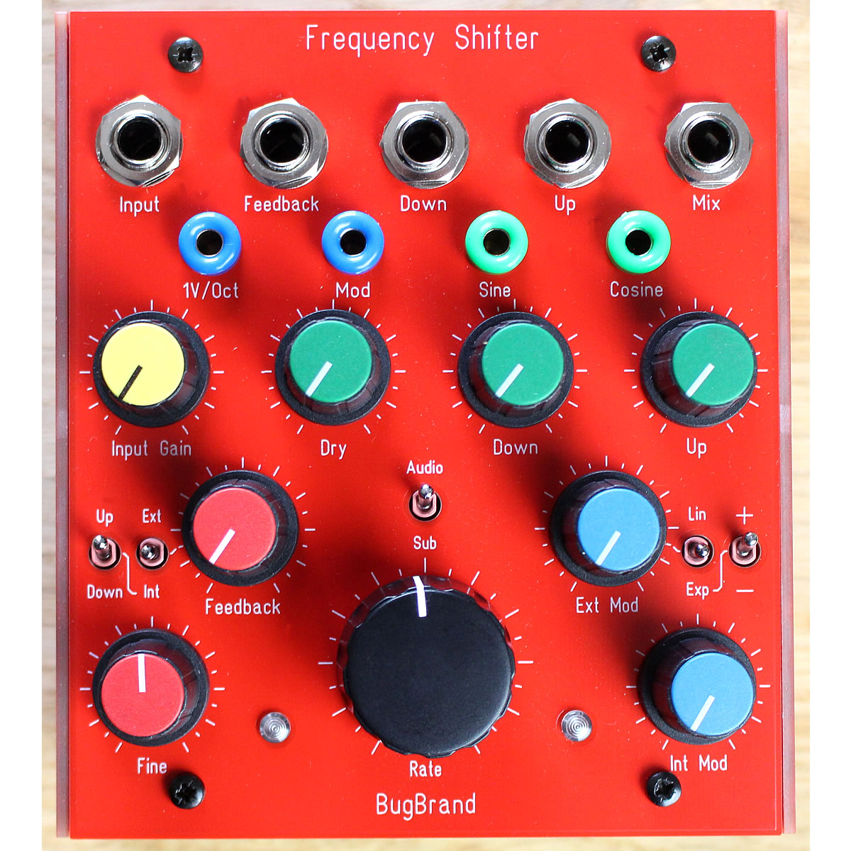
The Frequency Shifter (red) is a powerful and experimental analogue processor. This standalone design springs from my Quadrature Sine and its Frequency Shifter Expander modular designs – all wrapped up with circuitry & features to allow it to fit snugly into more regular studio processing roles. It will transform your audio streams in otherworldly ways – clangorous, tonal, phased, stereofication and swoosh.
An important starting clarification is that Frequency Shifting (FS) is not the same as Pitch Shifting (PS)
- FS is linear addition or subtraction, where frequencies are shifted up or down by a fixed amount – this tends to disrupt harmonic relationships, certainly for any complex waveform.
For example, if an input signal of a 100Hz sine wave is shifted with a 50Hz signal, the Down output will be 50Hz (100Hz – 50Hz) while the Up output will be 150Hz (100Hz + 50Hz). If the input signal was changed to 200Hz then the outputs would be 150Hz (Down) and 250Hz (Up). - PS, on the other hand, is multiplication and retains harmonic relationships – it can only be done digitally.
For example, a C major input may be multiplied by 2 semitones to take it up to D major, whereas if the input was a G then it would shift up to an A.
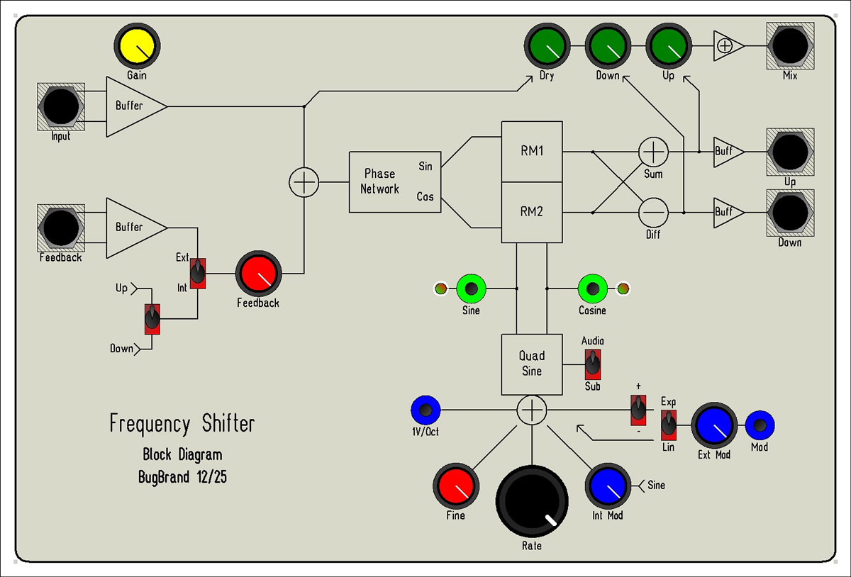
There are two main core circuit areas within the Frequency Shifter along with some preamps/mixers/buffers to wrap things up nicely for your audio lines – have a check of the Block Diagram above.
- the main audio route (after preamps & feedback – see below) combines a special phase shifting network, known as a Dome Filter, two Balanced Modulators (aka Ring Modulators) and sum/difference stages – all need to be particularly precise in their component selections and calibration!
- the dome filter is an 12 stage all-pass network covering the full audio spectrum which shifts input signals by +/- 45° (ie. 90° phase difference)
- the balance modulators multiply these shifted signals with the Sine/Cosine waveforms from the Quadrature Sine generator
- the outputs of the modulators are then summed to give an up shift and subtracted to give a down shift
- the Quadrature Sine is a precision Voltage Controlled Oscillator which outputs pure sine waves that are 90 degrees out of phase
- it can be run at audio (15Hz to 20kHz+) or sub-audio rates (0.2Hz to 20Hz – see note below) – these ranges can be extended with external CV
- the main Rate control covers 10 octaves, while the Fine control covers 1 octave
- there is a 1V/Oct banana input for accurate pitch tracking over several octaves from an external source/controller – the design is temperature compensated for stability
- the Ext(ernal) Mod input, which is fed from the Mod banana socket, can be switched to either Linear FM (AC-coupled) or Exponential (like 1V/Oct) – the Exp setting has a polarity switch
- the Int(ernal) Mod control feeds the Sine output back into the exponential summer and bends the waveforms – this shifts frequencies downwards and gives particularly experimental audio results
- the two waveforms are indicated on two Bi-Colour LEDs and full amplitude waveforms (+/-5V) are presented on the Sine/Cosine banana sockets
- NOTE – in Sub audio mode, the oscillations have to build up to full amplitude when the devices is first switched after power-up – turn the Rate control up full until the LEDs are blinking strongly, before turning down to the desired rate. Once this oscillation has been built up, you can switch freely between Audio/Sub rates.
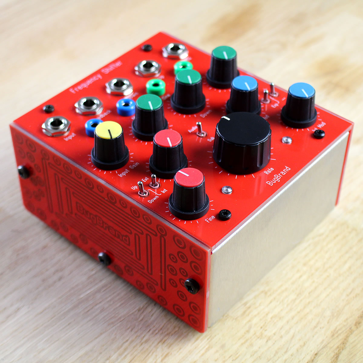
- the circuit wrappings consist of balanced preamps, mixing stages and output buffers
- the main audio input, on electronically balanced 1/4″ socket has variable gain up to 20dB – for modular signals, just keep the input gain low (c.9 o’clock). There is soft clipping that can be nicely overdriven
- the feedback input is also a balanced 1/4″ socket but without variable gain. The feedback route can be switched between External or Internal, where the Down or Up signal is fed back around for rich timbres. There is further soft limiting around the mixer stage where the dry and feedback signals are combined.
- all outputs are on impedance balanced 1/4″ socket – the Down & Up outputs feed direct from the sum/diff stages, while the Mix output combines a mix of Dry, Down and Up
So how does it sound? How might it be used? Some ideas & demo sounds:
- due to the internal Balanced Modulators, audio results can often be clangorous or unharmonic, just as with ring-modulators. Pure sinewave inputs can be treated with clearer harmonic approaches, especially if also tracking with 1V/Oct, but most input signals will be more complex with harmonic spectra that will naturally interact with the linear shifts – you have to use this to your creative advantage! Certain tunings will provide rich thickening on specific chords and more dischord on others
- the various outputs can be used for stereo spatialisation – for example, the dry signal (eg Mix with only Dry turned up) could be panned central, while Down and Up go to left and right
- sub-audio rates are most akin to phasing, especially useful with the above stereo approach
- internal feedback adds a *lot* of thickening and potential screech – especially rich in sub-audio rates
- external feedback can be experimented by patching a process (eg. delay) from one of the direct outputs (Down or Up) and back into external Feedback input
The following demo sounds were recorded simply – a mono source being processed via a mixer & aux-send, with Down and Up outputs returning to separate channels. The signals are then panned so that Dry is central, while Down is Left and Up is Right – headphones may be helpful in listening. Throughout I keep the sound source constant and only alter the Frequency Shifter controls, including using 1V/Oct tracking from an external keyboard controller.
Technical Specifications:
Inputs – Mono balanced 1/4″ Jack – impedance 20k Ohms
Outputs – Mono Impedance-balanced 1/4″ Jack – impedance 100 Ohms
CV inputs – 4mm Banana – impedance 100k Ohms
CV outputs – 4mm Banana – impedance 470 Ohms
Module current draw – +ve 60mA, -ve 55mA
Power – 12V DC 300mA supply, centre-positive, 2.1mm connector.
(worldwide 90-240VAC wall-wart provided with interchangeable mains plug adaptors)
The Frequency Shifter is enclosed in a custom aluminium case (based on the Modular line) with PCB material front and side panels. It is a ‘module’ so will happily slot into the Powered Frame.
Dimensions approx 5.25″ x 5″ x 3.5″
Two year parts warranty.
Instruction manual PDF
Price: £430 (+ VAT in UK -> £516 inc.) + Shipping
Also available as an uncased module version for £385 (+ VAT in UK -> £462 inc)
![Spring Tanker [Archive]](https://www.bugbrand.co.uk/wp-content/uploads/2019/10/SpringTanker_LRG-360x360.jpg)